

『Flow Meter Revit Family Architecture: Standard Mechanical Piping Components for HVAC Layouts』Related information(flow rotameter|digital flow meter|balo meter|hydraulic flow meter|volumetric meter|positive displacement meter|pitot tube flow meter|displacement meter|cfm meter|variable area flow meter|inline flow meter|differential pressure flow meter|calibrated flow meter|velocity meter|paddle wheel flow meter|oval gear flow meter|anemometer hvac|multiphase flow meter|doppler flow meter|thorpe tube flowmeter|heat flow meter)
Flow Meter Revit Family Architecture: Standard Mechanical Piping Components for HVAC Layouts
Quick Answer
Silver Automation Instruments provides Revit families for flow meters used in HVAC chilled water, hot water, condenser water, fuel oil, steam, and compressed air lines. Each family uses standard mechanical piping connectors and shared parameters. Send us your pipe size, fluid, pressure, temperature, and flow range if you need a model or a quotation.
Why Revit Families Matter for HVAC Flow Meter Layouts
HVAC designers often model pumps, chillers, valves, and strainers but leave flow meters as a generic box. In practice that generic box creates clashes. The real instrument has a transmitter housing, a neck, and a required clearance above the pipe. A DN100 electromagnetic flow meter may have a face-to-face dimension of 250 mm and a transmitter height of 180 mm from pipe centerline. If the Revit family does not show this, the contractor finds a problem during installation.
We build our flow meter Revit families from the same drawings we use for the physical product. The geometry is not a simplified cylinder. It includes the sensor body, flanges, terminal box, and transmitter. Because we model LOD 350 geometry, the file is light enough for large mechanical rooms and detailed enough for clash detection in Navisworks.
Revit Family Architecture and Standard Mechanical Piping Components
Our Revit family architecture starts with the pipe connector. Each family contains pipe connectors with the correct system classification. A chilled water meter uses a Hydronic Supply or Hydronic Return connector. A fuel oil meter uses a piping system set to diesel or light fuel oil. A compressed air meter uses a gas or air system. This keeps the flow meter connected to the correct system in Revit and prevents orphaned connectors.
The family uses shared parameters for tag number, model, DN size, flow range, manufacturer, and pressure class. Our file naming follows a simple pattern: Silver_DN80_Electromagnetic_Class150. The face-to-face dimension, flange standard, and clearance zones match our datasheets. No generic placeholder dimensions.
Most engineers skip this step. They place a flow meter family, then replace dimensions later. That creates rework. An HVAC contractor in Singapore spent two days reworking a chilled water spool because the bid model showed a short inline device. The actual DN150 electromagnetic flow meter needed 300 mm face-to-face length and 250 mm clearance above the transmitter.
Parameters That Match Physical Instruments
For a DN80 electromagnetic flow meter, the family uses a 200 mm face-to-face dimension, 80 mm process connections, and a 145 mm height from centerline to transmitter top. The flange standard is ASME B16.5 Class 150 RF or PN16 depending on the project. The electrical entry can be rotated in 90 degree increments. The liner is PTFE or EPDM depending on the fluid. The electrodes are 316L, Hastelloy C, or titanium for seawater and chemical dosing lines.
For a DN50 thermal mass flow meter on compressed air, the family includes an insertion probe depth of 50 mm and a ball valve port. The process connection is 1/2 inch NPT. The transmitter sits 120 mm above the pipe. The model includes a 200 mm clearance zone for probe extraction. That allows maintenance without removing the meter from the line.
Selection by Flow Meter Type
Electromagnetic flow meters cover chilled water, hot water, condenser water, cooling tower makeup, and raw water from DN15 to DN600. They need a minimum conductivity of 5 µS/cm. A typical HVAC chilled water specification is 0.1 to 10 m/s flow velocity, 6 to 10 bar pressure, and 2 to 40 degrees Celsius. The model output is 4-20 mA HART plus pulse. Optional MODBUS RTU and a PT100 temperature sensor are available for energy monitoring.
For steam lines, vortex flow meters cover DN20 to DN300. A typical steam meter reads
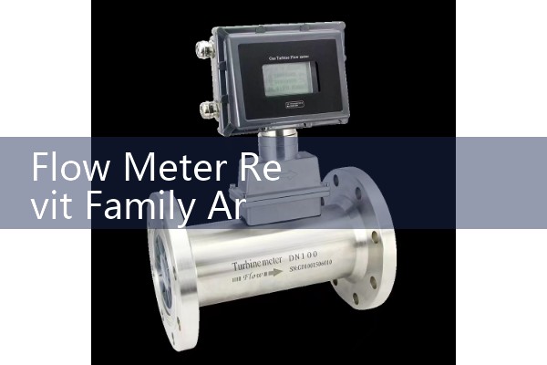
Oval gear flow meters suit diesel, fuel oil, and light lubricants from DN10 to DN100. Viscosity up to 1000 cP is fine. A Vietnamese shipyard used our DN25 oval gear family for a diesel transfer skid. The model included a strainer and an air eliminator. The transmitter was ATEX Zone 1 rated. Flow range was 1 to 10 L/min. The process connection was BSPP 1 inch. The tag number sat inside the shared parameter field.
Ultrasonic flow meters fit existing pipes without cutting the line. We provide inline and clamp-on families. For a district cooling plant in Manila, the model used a DN300 inline ultrasonic flow meter with 500 mm face-to-face dimension and 300 mm side clearance. The meter measured 500 to 5000 m3/h. Output was 4-20 mA HART and MODBUS RTU. The pipe material was carbon steel schedule 40.
Installation Notes for Mechanical Engineers
Keep straight run upstream and downstream. For an electromagnetic flow meter, keep 5D upstream and 2D downstream from the nearest elbow or pump. D is the pipe inner diameter. For vortex meters on steam, keep 15D upstream and 5D downstream from a control valve. The Revit family includes a clearance zone for this but the engineer should check the overall spool.
Do not place an electromagnetic flow meter at the high point of a chilled water line. Air pockets cause unstable readings. The meter body must stay full of liquid. For horizontal lines, mount the transmitter to the side. For vertical lines, flow can go upward or downward. Avoid downward flow with open discharge. These details are in our model notes and the product datasheet.
How We Deliver the Revit Family Files
We send the Revit family by email or through Autodesk Construction Cloud. The file format is RFA for Revit 2022 and Revit 2024. We also send a TXT shared parameter file and a PDF with dimension tables. If your project uses Revit 2021, tell us before ordering. Because older templates handle pipe connector parameters differently.
There is no charge for standard Revit families with a quoted instrument. We can send a simplified LOD 200 version for design development before purchase. The LOD 350 version follows the paid quotation.
FAQ
Question: Do you provide Revit families for all Silver Instruments flow meters?
Answer: Yes. We provide families for electromagnetic, ultrasonic, vortex, oval gear, thermal mass, and Coriolis meters. Each family follows the same shared parameter set and connector logic.
Question: What pipe standards do the families support?
Answer: We support ASME B16.5 Class 150 and 300, PN10, PN16, PN40, BSPP, NPT, and Tri-Clamp. Send us the pipe standard and DN size so we match the flanges correctly.
Question: Can the Revit family include a bypass loop?
Answer: Yes. For oval gear flow meters and small fuel oil lines, we can model a bypass loop with strainer and valves. This is common for diesel generator and boiler fuel systems.
Question: How accurate are the clearance zones?
Answer: Clearance zones follow the physical transmitter and removal envelope. For an electromagnetic flow meter, we include 200 to 300 mm above the transmitter. For a clamp-on ultrasonic meter, we include 150 mm side access. These dimensions come from the product drawings, not generic estimates.
Question: What information do you need for a quote?
Answer: Send us your pressure in bar, temperature in degrees Celsius, pipe size in DN, flow range, and fluid. Include the Revit version and pipe standard. We will send a model and a quotation within 24 hours on working days.
Contact Silver Instruments for flow meter Revit families and pricing. Tel: +86-135-1213-1526. WhatsApp: 86-135-12131526. WeChat: +86 13512131526. Our website is flow-meter.com.au.
 Hot Blog
 Related AD